Pages

Friday, April 24, 2009

F5 Part 7

Well it's been over two months since my last posting. I have been very busy getting my garden finished.
Since I was last here I have completed a base place for the rectifiers and just this evening, I managed to actually get the two main heat sink plates on. This turned out to be a tough decision as I hadn't really thought about the process of attaching the output devices to the slab of H/S. As it turned out I tapped two holes 104mm apart for the M3 screws. If I can't get the board to match up, I'll just wire them to the boards.
I have also been rather busy trying to get my speakers to some sort of stage were I could get them out of the garage and into the lounge, so it's been a busy couple of weeks.


Yes they are monsters, I had no idea that they would look this big. But the wife has said very little about them, so big relief.
The Image speakers sitting next to them are just over 1m high so it shows how large they are.


The rear was made into a box (covered in cork) to place the X/O's in and also create two side
bits to place two bags of 'shot' in. So as to give a little stability to the base. The lid fits snug on top. The front panels are cheap (well cheapish) pine which I coated in oil (4 coats). I used two cable glands (one at the front and one at the rear) to hold the speaker leads in place. Bugger paying ridiculous amounts of money for fancy connections that hardly ever get used. These turned out to be about $3 dollars each as opposed to $140 for fancy ones........


Don't even have an amp to drive the bass drivers yet. That'll be a long way off.

Right ........back to the amp.


Right..............you can see the two side plates have been attached and I also put the two thermistors (see power supply schematic on Nelsons page) down the back by the ground. And also put in a power switch, which was originally going to go in the front. But I have decided to keep this nice and clean, not even an LED is going to find it's way onto that nice piece of wood.


Fourteen screws and washes later.............. I placed some silicon and the back as well to try and make good contact between the two surfaces.


Saturday, February 14, 2009

F5 Part 6

I finally got around to tackling the base, which houses the caps and the fans. I sort of started of with the intention of only putting in a block for he earths. But as it turned out i started marking other bits out on the board as well.


On previous builds, (as I've said earlier) I've tended to just go for it. But this time I decided that since I had the base plate off, I may as well mark everything out. So that's what I did. Masking tape everywhere as tried to make sure nothing was missed. Even drilled the holes for the feet(which I may change later). The hadest part was drilling the holes for the fans, which took the longest time as they were 90mm diameter. And the the old Ryobi just hasn't got the guts to drill too fast through this stuff. I also find that the plastic gets so hot it sticks to the teeth, making it difficult to cut. So you have to keep pulling the drill bit out and the go again.


And another thing. Most of the pics I take seem to be at night time so they are always out of focus, sorry about that. After all the holes were cut I placed things back on the board just to check everything did actually fit. And i still had room left over.


The aluminium plate at the top of the picture was made to hold the bridge rectifiers. It's 75mm x 300mm x 8mm. So I hope it will do. I lifted it off the with the use of some 40mm M3 screws, so that it gets some air underneath it.
Everything seem to fit o.k, but the fans were about 3mm different, but I'm hoping no one will notice.

And a picture of the underside of the case with the bottom back in. You will also note I have installed a cable gland. I felt this to be much easier to install than one of those IEC/ICE/IEU..........bla,bla,bla things. As this only meant getting out the spade bit and drilling one hole. And once the thing is up and running it's not going to be moved around anywhere, or need to be unplugged copious amounts of time so why spend the extra money and time on something that's just there to look good.


And here is the inside before i placed the caps back in.


Thursday, February 12, 2009

F5 Part 5

I had some free time today so I cut the cap block in two and sanded it. I didn't go crazy with the sanding, just enough to clean them up. I had some clear varnish in the garage so I wacked two coats on. And yes I skinned the caps, as they were a very tight fit I would have ended up sanding the inside of the holes. This way they fit snug without being too tight.


They should do the trick. I didn't want to get too carried away with them.


I haven't worked out exactly where they'll go yet. Like I said before, nothing is truly planned for. But i will need enough space for four bridge rectifiers and a heat sink.


I hope I don't run out of space................................;)

Saturday, February 7, 2009

F5 Part 4

So I actually had quite a good weekend, in between taking my boy out for walks. I managed to start on the next part, the blocks that will hold the caps in.
Remember on the previous page I talked about not having much of a plan, well things tend to go a little astray and this part was a good example. I started off wanting to use two layers of plastic, one to hold the caps in place at the bottom and another to them in place at the top. I was going to make up some small spacers to attach to the upper and lower plates to keep them together. But halfway through marking them out I spotted a piece of wood sitting on the window ledge in the garage and thought,
"What if I just had one block, and drill the holes deep enough to hold the caps in place?"
Once they are all wired together, i'm sure they would hold.


This is as far as I got with the first attempt. You can see it's a mess on the bench and it doesn't get any better.


This is my expensive milling equipment. A $69 drill press sitting on the floor. This is as high tech as it gets for me.


Made a start on the blocks. Actually, this is an off-cut from the front panel. It's a tight fit, but hopefully all the holes will be o.k. There is a slight gap in the middle, this is where the resistors will sit.


It's a tight fit, but I think they should be fine. I haven't made up my mind if I should skin the caps or not. I will wait and see when everything is drill sanded and coated, to see how they all fit.

Friday, February 6, 2009

F5 Part 3

I've been quite busy over the couple of weeks, xmas and family. I have also been trying to build a pre-amp, which hasn't turned out that great and will need lots of work done to get it up and running to drive the F5.
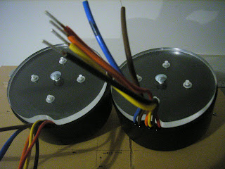
My next step was to construct a couple of plates for the transformers to sit on. I needed to make something that would allow me to attach them to the front panel. The good thing about using wood, is that you can easily screw things into it. I have heaps of plastic at home, as you may have noticed, so it was a no brainer to construct them out of that.


I had to cut a little piece out at the bottom to allow the cable to sit into so as not to get crushed when I screwed them down to the base of the front panel.


I placed some washes under them as the bolt for the transformers was not countersunk enough, which didn't worry me as no one would see it anyway. Note the really high tech and accurate alignment method I used for the two base plates? Masking tape............I just use what I've got and I usually make it up as I go along. I have a fair idea in my head what it's all going to look like, but until I sit down at my little desk in the garage, I don't really know how I'm going to go about it. In fact I don't even have a plan drawn out or anything measured up. Which is a bit silly as I've made 3 other ChipAmps and after each one, I tell myself to plan and draw up the next one before I start cutting anything, but it never happens......
What ever happens...happens...........hehe.


Wow look.............. I even bought some of that there special screw thingy's with nylon in so they will lock down, well I think they will.


These will have to be taken out again at some stage before final fitting, and when I put in the rest of the power supply.


I even had time to cut the holes for the input and output connections. Although in my rush to get them done, I messed up the RCA holes. Perspex is really easy to damage and I did just that. I managed to split the edges, so I placed a couple really big washes on both sides of them to cover it up.

O.K so the next post will be regarding the caps and the power supply.............see ya


Sunday, January 11, 2009

F5 Part 2

The next stage was cutting the top and bottom. These were made from 10mm Perspex, which I managed to get hold of a while back and keep aside. It really makes a mess when cutting and sanding, so do it outside if you intend to work with this stuff. The rear panel was also plastic, it's all I had, and aluminium was completely out of the question as it's just too expensive here. So here are some pics of the top/bottom and rear panels


Check those sexy screws out on the top panel. They are actually gib fixing screws. I needed something that would self tap into the brackets. I will sand them back later on.All the others are M3.


I thought I'd just slip this pic in, as I took it at the same time. These are the feet I'll be using. I bought these from http://www.madisound.com


These are quite nice and long, which I thought would be needed as this is such a big case that smaller ones would have looked too small.